SketchUp for woodworking: modeling furniture parts and joinery
Draw each board at its finished size, keep joinery inside its component, and take shop dimensions from an assembled master. Save exploded views in a separate file.
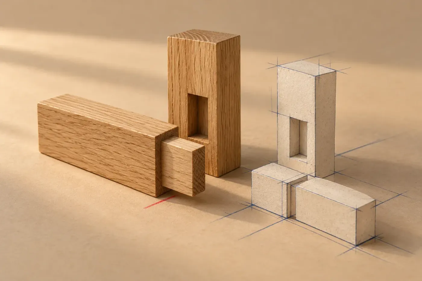
Use SketchUp for woodworking by drawing each board at its finished size and turning it into a component before it touches another part. Add joinery inside those components, then take shop dimensions from the assembled model. I'd keep the exploded view in a separate SKP file because moving the boards apart won't disturb the assembly you measure and count.
The steps below use desktop SketchUp Pro on Windows or Mac; SketchUp 2027 needs Windows 11 or an Apple silicon Mac. Pro includes LayOut and access to extensions, so this route covers both a dimensioned model and a scaled drawing sheet. Two parts of it need Pro rather than Go, which runs only on iPad and the web: the LayOut sheet and the cut-list extension. The comparison of Free, Go, Pro and Studio shows what else each plan includes.
Choose the shop views before drawing the first board
Plan for a Top view to show the footprint, a Front view for height and rail positions, and a Joint detail close-up. Those belong to the assembled master, furniture.skp. An Assembly exploded view will belong to a second file.
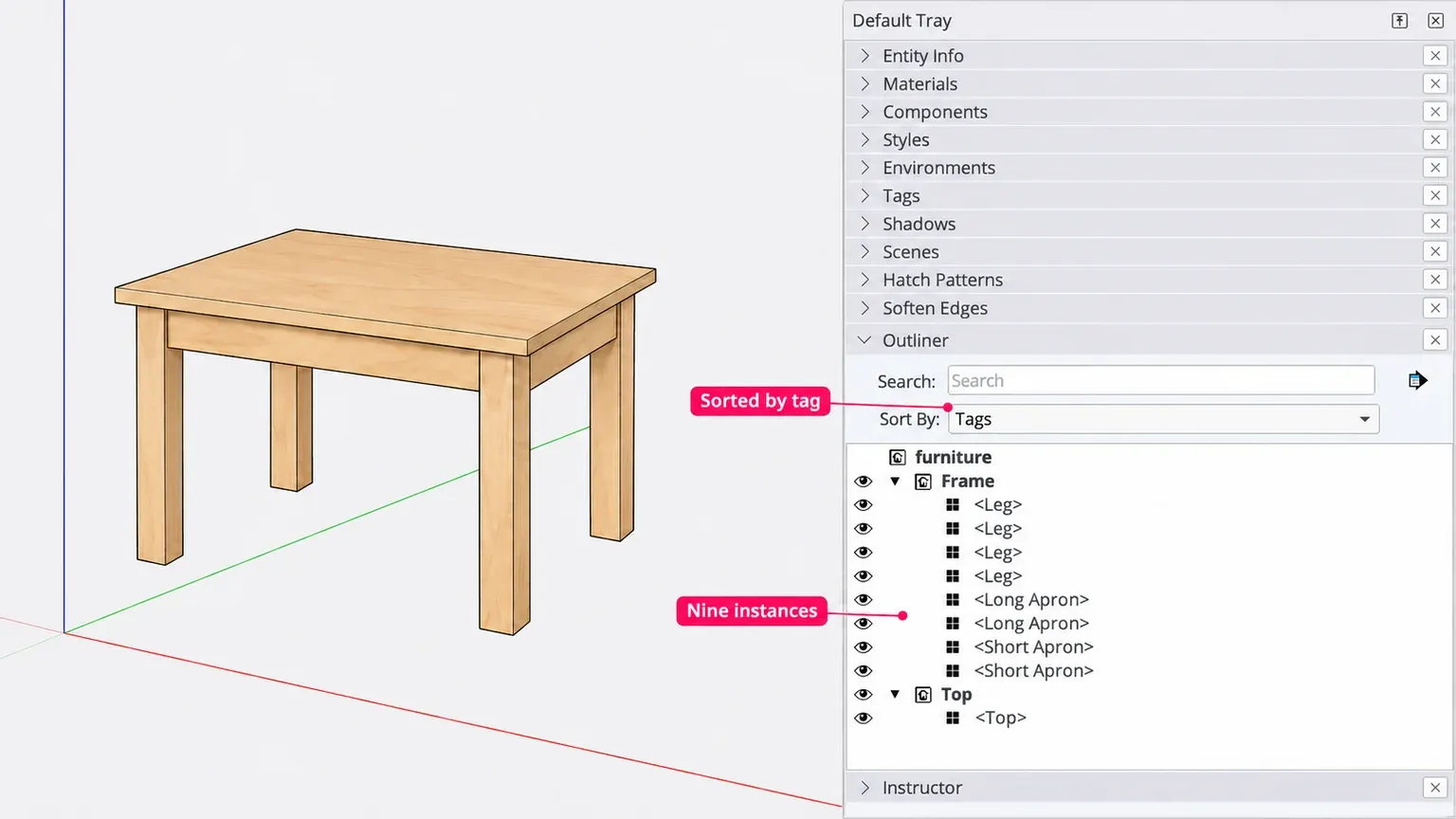
Give each physical board its own component instance. Identical boards can share one definition; boards with different lengths or joinery need separate definitions. For the small table below, that means a top, four legs, two long aprons and two short aprons. If your top is modeled as individual boards, keep those boards separate too.
Put the top container on a Top tag and the leg and apron containers on Frame. Keep the edges and faces inside them Untagged: tags control visibility, while the component boundary keeps one board's geometry separate from the next. For cupboard carcasses and their room layout, continue with cabinet design in the design projects collection.
Draw one board at its finished size and wrap it
Use the thickness and width of the stock you intend to work with. The following dimensions are a practice example, not standard board or joint sizes.
- Open Window > Model Info > Units. Choose the units and display precision you need. Explicit units in a typed value let you enter
19mmeven when the model uses another unit. - Choose Front from the Camera menu's standard views to face a vertical drawing plane. Press R for Rectangle, click a first corner and move diagonally across that plane. Enter
19mm,70mm, then press Enter or Return. Check that the closed end face is 19 mm across and 70 mm high; Rectangle takes a length and width separated by a comma. - Press P for Push/Pull, click that face and establish the horizontal direction along the board. Click to set the extrusion, type
400mmand confirm. Push/Pull accepts an exact extrusion depth after you set its direction. - Press Spacebar for Select and triple-click a face of this still-isolated board to select its connected geometry. Choose Edit > Make Component, name the Definition
Rail, leave Replace Selection with Component enabled and click Create. These component settings wrap the selected geometry into one reusable part.
To check the size, open the component, select an edge and read its length in Entity Info. You can also hover over an edge with Tape Measure. Don't type a replacement value during that check: entering a number after a Tape Measure measurement can start a model-resize operation.
For another identical board, open the Components panel, find your existing definition, select it and click in the drawing area to place another instance. Close any component editing context before positioning the whole board. With Move (M), pick a reference point on the component and move it toward its destination. Wait for the required colored-axis inference; hold Shift to lock it, then enter the distance when you need a measured spacing. Move also aligns one reference point with another for a point-to-point placement.
Editing the geometry inside Rail changes every instance of that definition. If just one rail needs a different end joint, context-click that instance and choose Make Unique before editing it. Then double-click it or choose Edit Component; click outside when you're finished.
Model the joint inside the two boards
Use a 19 × 70 mm rail with a 400 mm body for this exercise. Its centered tenon will be 10 × 40 mm and project 25 mm from one end. That leaves 4.5 mm shoulders on the two thickness sides and 15 mm above and below the tenon. The rail's overall length becomes 425 mm; adding the same tenon at both ends would make it 450 mm. Choose the actual joint sizing and clearance for your timber, tools and project.
Pull the tenon from the rail end
- Open the rail component for editing. Choose Tape Measure from the Tools menu and check that its cursor shows guide-line mode. Click on an end-face edge, move perpendicular to it and enter an offset. Tape Measure guides don't split the board's faces.
- Place guides 4.5 mm inward from the two thickness edges and 15 mm inward from the top and bottom of the 19 × 70 mm end. Use Rectangle at the guide intersections to close the central 10 × 40 mm face.
- With Push/Pull, click that central face, pull away from the board, set the direction and enter
25mm. Confirm the tenon has four shoulders and check an exposed length edge in Entity Info. Close the component context.

Check the overlap before cutting the mortise
Make an example leg with a 70 × 70 mm end and a 500 mm extrusion, using the same Rectangle, Push/Pull and Make Component sequence. Draw its end in Top view and pull vertically. Inside the leg, mark a future 10 × 40 mm mortise on a 70 mm-wide side face: 30 mm in from each side, with its top 15 mm below the leg top. Leave the leg uncut for this check.
With both components closed, Move the rail by a corner at the root of its tenon to the corresponding mortise-guide intersection. The rail top should align with the leg top, its shoulder should meet the leg face, and its tenon should enter the still-solid leg. Save the assembled master.
- Choose File > Save As and save a scratch copy named
furniture-joint-check.skp. Intersect consumes the geometry outside the overlap, so run it only in this copy. - Select each board and check that Entity Info calls it a solid. Solid Tools require a finite closed volume, with no missing faces.
- Select both components, context-click and choose Solid Tools > Intersect, not Procedural Intersect. The shape that remains is the shared volume of the tenon and the uncut leg: the future pocket.
Intersect doesn't leave a leg with a mortise. A completed matching mortise may leave the two parts merely touching, so this positive overlap check belongs before the pocket is cut. Close the scratch copy, choose File > Open and select furniture.skp for the next step.
Push the mortise and dado into their own parts
Open the leg component, making it unique first if its joinery must differ from the other legs. On the marked face, close the 10 × 40 mm rectangle between the guides. Select Push/Pull, click the rectangle and move inward into the leg. Click to set that direction, enter 25mm and confirm. The partway Push/Pull cut should leave a stopped pocket. Check the opening and an accessible depth edge before closing the component.
A dado uses the same closed-face method. For a separate example of a 19 mm-thick panel receiving a 19 mm-thick divider, work inside the panel component and mark a 19 mm-wide strip across its broad face. Close the strip with Rectangle, push that face inward and enter 6mm. Check the groove width and depth against those example values; replace them with your measured stock and chosen joint dimensions.
Finish the part shapes before adding decorative profiles with Follow Me or aligning the visible wood grain direction. A convincing texture won't verify the joint dimensions.
Move the assembly apart in a separate file
Save the completed assembly as furniture.skp, then use File > Save As to create furniture-exploded.skp. A scene saves camera and visibility settings, rather than an alternative set of board positions. Moving a leg in the same model moves it for every scene.
In the exploded copy, select whole components and use Move to lift the top and spread the legs and aprons along their appropriate axes. Establish an axis direction, lock its colored inference with Shift if needed, and type a distance that makes the parts clear. Keep the boards intact: the Explode command breaks a component into its entities, which isn't the operation you want for an assembly view.
Set the camera and tag visibility, open the Scenes panel and click Add Scenes. Use Show Details to name the scene Assembly exploded and retain its camera and visible-tag properties. Saved scene properties let you return to that view after orbiting. Keep this file separate from the master used for part counts.

Dimension the model, then choose the drawing route
Keep dimensioned scenes in SketchUp
Return to the assembled master. Choose Tools > Dimensions, click a model endpoint, move until the inference highlights the intended second endpoint and click again. Pull the dimension away perpendicular to the measured edge, then click to place it. Dimensions linked to model geometry update with the part; manually replacing their text stops that dynamic update.
Dimension the lengths you need to make the parts: the rail body between shoulders, its overall length including tenons, stock thickness and width, and the joint positions. Those are different measurements. Give the joint close-up enough space to distinguish the pocket depth from its height.
Choose Top or Front from the Camera menu's standard views, then Camera > Parallel Projection for an orthographic view. Place the useful dimensions where they can be read. Add and name scenes Top shop drawing, Front shop drawing and Joint detail after framing each view. Check that selecting a scene brings back the intended camera and visible parts.
Use Pro LayOut for a scaled sheet
- Save the master, choose File > Send to LayOut and select the document you want to create. LayOut opens a viewport containing the model.
- Select that viewport. In the SketchUp Model panel, under Viewport, use the Scene dropdown to choose the saved shop view.
- In the same panel, click Ortho, then choose the viewport scale that suits the sheet. Check the view and scale on each viewport you use.
- For dimensions added in LayOut, choose Tools > Dimensions > Linear. Snap both ends to model points, move the dimension outward and click to finish. A dimension that mixes a model point with a paper-space point reports a paper-space distance. Compare a known board length with the dimension shown before relying on the sheet.
Check a cut list against the assembled model
A woodworking cut-list extension is an optional third-party step. OpenCutList reads component bounding boxes, not groups, to derive visible-part dimensions. Its automatic interpretation treats the longest dimension as length and the smallest as thickness; another mode reads length, width and thickness along the component's local red, green and blue axes.
The OpenCutList documentation covers version 7.1.0 and later and may describe features that haven't been released. Its installation page lists desktop compatibility from SketchUp 2017 onward, with some advanced features unavailable before 2021, and excludes online and iPad editions. Check your specific SketchUp and extension release rather than assuming that baseline certifies every current platform combination. The extension code is licensed under GNU GPLv3.
Check a list against one known component before using it for stock planning. The practice rail with one tenon has a 425 mm bounding length, although its body is 400 mm; the two-tenon version would be 450 mm overall. Confirm the extension's length direction, width, thickness and quantity. Make sure all intended boards are visible or included in the chosen selection, and use only the assembled master so scratch and exploded copies don't add duplicate parts.
Use the rail's 425 mm as the finished overall length. Before buying timber, check OpenCutList's allowances for solid wood: its material settings hold actual raw-stock thicknesses, oversizes in length, width and thickness, and a waste allowance. Set those for your timber and machining process, then check the raw-material estimate separately from the finished-parts list.
Return to Front shop drawing, check the rail and joint dimensions, and use Update Scene if you've changed its view. Choose File > Save. That named scene is the view to return to when you take the model to the shop.