Kitchen and cabinet design in SketchUp with reusable components
Build a measured kitchen layout with reusable cabinet envelopes, separate width variants and checked appliances, then save a top plan and each wall elevation.
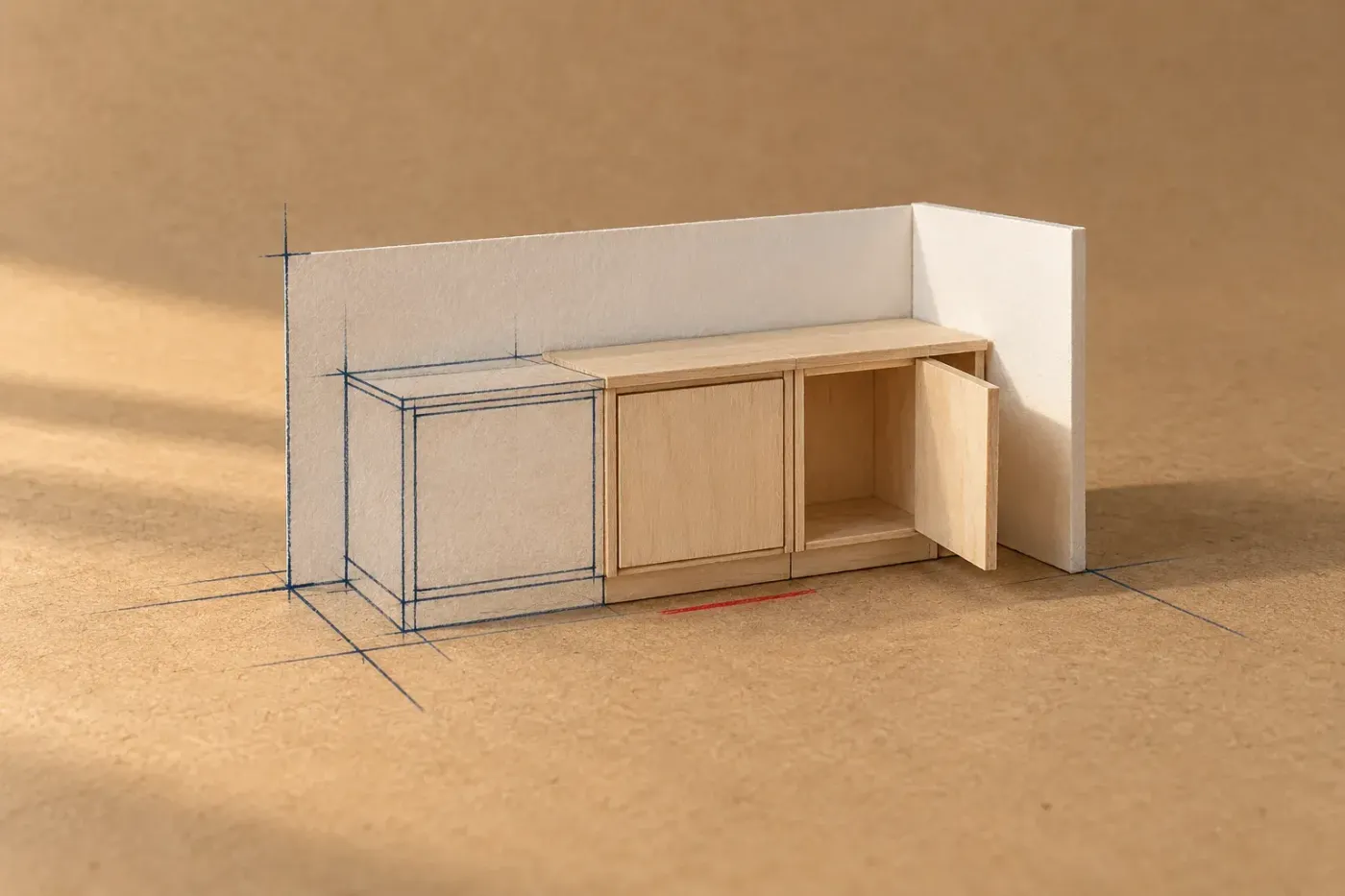
Build your SketchUp kitchen design at real size, using a grouped room shell and reusable cabinet components. Keep equal cabinets linked to one definition, make a different-width cabinet unique, then save a top plan and an elevation for each cabinet wall. SketchUp suits the layout stage of a kitchen: a measured run stays editable, and the same model gives you the plan and every wall view. It stops where the envelopes stop: order lists and cut lists need real cabinet parts, which the woodworking route builds, or a cut-list extension. I'd begin with plain cabinet envelopes because they make the occupied space easy to change before panel thicknesses, doors and hardware complicate the model.
Leave the project with scenes named Kitchen Plan, Sink Wall and the names of your other cabinet walls. The room shell belongs in a group, repeated cabinets in components, the worktop in its own group and each appliance in a separate component. Put visibility tags on those containers; leave their raw edges and faces Untagged, since tags don't keep touching geometry apart.
The steps below use SketchUp for Desktop 2027 on Windows or Mac, which needs Windows 11 or an Apple silicon Mac; Intel Macs stay on 2026.2. Confirm each typed value with Enter on Windows or Return on Mac. Pro includes the desktop modeler and LayOut; Go covers web and iPad. Dynamic Components are listed with Pro and Studio, but the plain-component route here doesn't depend on a configurable cabinet library.
Measure the room before choosing the cabinet run
Record the internal wall lengths, ceiling height, corners that aren't square, door openings and swings, window position and sill height. Mark the plumbing and other fixed services from the same reference corner. Use the selected appliance manufacturer's installation instructions for service space, ventilation and opening clearances. A box that fits between two walls can still leave a door unable to open.
For this example, the room is 3600mm by 3000mm, with a 2400mm wall height. The cabinet envelope will be 600mm wide, 600mm deep and 720mm high. These are teaching dimensions, not cabinet standards or a specification for your room. Replace them with your survey and the maker's overall sizes, accounting for the plinth, worktop and fillers where they occupy space.
- Click the Model Info link in the Status Bar, then select Units. Choose Decimal and Millimeters for length. The Units settings control the model's measurements; explicit entries such as
600mmalso identify the unit when a different template is open. - Start with an empty modeling area. Activate Rectangle with
R, click the origin, move diagonally across the red-green ground plane and click the opposite corner. Immediately type3600mm,3000mmand confirm. Rectangle accepts a length and width separated by a comma. Check both floor edges before continuing. - For a simple wall face, activate Line with
L. Click a floor corner at its Endpoint inference, move up the blue axis, type2400mmand confirm. From that upper endpoint, draw along the wall's red or green direction for its measured length, then join the new upper corner to the corresponding floor corner. The closed edges should form a vertical face. Repeat for the walls the layout needs. - Select the room's floor and wall geometry, context-click and choose Make Group. Keep the shell separate before drawing cabinets. Open that group to add measured window outlines and fixed-point markers; click outside when finished. The broader interior design workflow covers developing the room beyond this layout shell.
Check a known edge with Tape Measure, shortcut T: hover over the edge and read its length in the Measurements box. For a distance between two specific points, tap Ctrl on Windows or Option on Mac until Tape Measure is in Measure mode, then click the two endpoints. Finish the check without typing a replacement length afterward: entering a value after a measurement can start a model-resize operation. A survey check should verify the room, not resize it.
Make one cabinet envelope into a component
Close the room group's editing context first. Draw the cabinet in clear space, where its loose edges won't join the shell. This first box represents occupied volume only. It contains no shelves, panel thickness, door swing or joinery.
- Press
R, click a ground-plane point, move diagonally and click again. Immediately type600mm,600mmand confirm. Two measured600mmedges and a filled face establish the footprint. - Activate Push/Pull with
P, click the footprint face and move upward. Type720mmand confirm. Push/Pull turns the face into a box with a typed extrusion distance. Check its height with Tape Measure. - Select all the box's faces and edges. Choose Edit > Make Component, or context-click the selection and choose Make Component. Enter
Cabinet Envelope 600in Definition, keep Replace Selection with Component selected and click Create. That checkbox replaces the selected geometry with a component instance.
A single click should now select the whole cabinet. Open the component only when you intend to edit its contents. A definition edit will reach its matching instances, which is useful for repeated cabinets and troublesome when only one cabinet should change.

Copy the repeated width, then separate the different width
Select the cabinet component and activate Move with M. Pick a lower corner at its Endpoint inference so you have a reliable placement point. Move that corner to the measured start of the run, using an axis inference or a known room reference point, and check its position against the fixed window and service locations.
To add an equal cabinet, select the placed component, press M and pick its lower corner. Tap Ctrl for Move-copy on Windows or Option for Move-copy on Mac. Move along the run's red or green axis, type 600mm and confirm. The copy remains an instance of the same definition. Check that the adjacent cabinet corners meet and that neither box overlaps the other. A longer run of equal units doesn't need one copy at a time: the guide to copy and array components shows the Measurements box entries that repeat the first copy.
For a 450mm cabinet, separate its definition before changing the geometry:
- Select the instance that needs the different width. Context-click it and choose Make Unique. In Entity Info, its Definition gains a suffix, identifying the separate definition created for that instance.
- Open that unique component for editing. On this plain solid envelope, use Push/Pull on an end face and move it inward toward the opposite end by
150mm. Confirm the value, then click outside the component. - Remeasure the new overall width: it should be
450mm. Check that depth and height remain600mmand720mm, and that a neighboring linked cabinet is still600mmwide. Move the remaining cabinets to the new end if the narrower box leaves a gap you don't intend to keep.
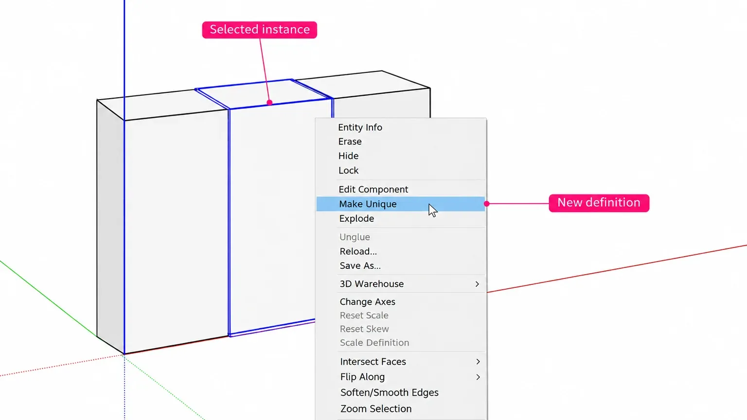
Use that end-face adjustment only on the simple envelope. A detailed cabinet needs its panels, doors and hardware edited to suit the new size. Scaling a whole component from outside changes only that instance, while editing geometry inside changes its definition. Neither operation guarantees sensible panel thicknesses or fitting positions, so once the layout is settled, switch to individual parts to build the cabinets.
Check an appliance before it enters the layout
Open 3D Warehouse from its desktop toolbar icon and search for the appliance's manufacturer and exact model. Inspect the producer, description, dimensions and applicable terms before downloading. A generic range model can suggest a shape; the selected product's installation drawing determines the space you must reserve.
Certified Content marks models checked against community quality and usability standards, but still compare the model with the current product specification.
For an SKP saved to your computer, choose File > Import to insert the downloaded component. Locate and select the file, then click Open. SketchUp loads it with Move active; click in clear space in the drawing area to place it before checking the size.
Keep the appliance as a separate component and measure its overall width, depth and height. Place it from a known corner against the room's measured references. If the size is wrong or the producer and terms are unclear, use a plain, correctly sized envelope until you have suitable content.
Keep the model's license information with the project when sharing it. The Warehouse terms distinguish incorporating a model into a combined work with substantial additional content from redistributing it on its own. A downloadable model isn't automatically yours to resell as a standalone cabinet or appliance asset.
Use Dynamic Components when their options match the cabinet
A Dynamic Component can save repeated manual changes when its author has exposed useful dimensions or presets. Select it and open Window > Component Options to inspect the available values. Configurable values and interactions depend on the component's variables; a downloaded cabinet isn't necessarily dynamic, and a dynamic cabinet doesn't necessarily expose width. Use the supplied options when they describe the cabinet you need, then recheck its size. Keep the ordinary-component route for envelopes whose geometry you control directly.
Add the worktop and the wall run
Draw the worktop, or countertop, once the base cabinets and under-counter appliances stand in their final positions, so one slab can span the whole run. Close every editing context first: drawn inside an open cabinet component, the worktop would join that definition and appear on every linked cabinet. The sizes below are teaching values; take the real overhang and thickness from the worktop you choose.
- Press
Rand click the top back corner at one end of the base run at its Endpoint inference. Move diagonally to the front of the far end and type the run length and the depth plus the front overhang, for example1650mm,620mmfor two600mmenvelopes and one450mmenvelope with a20mmoverhang. Check both edges with Tape Measure; if the values landed on the wrong edges, undo and type them the other way around. - Activate Push/Pull, click the new face, move upward and type the worktop thickness, for example
40mm. - Select all the worktop's faces and edges, context-click and choose Make Group. In the Tags panel, click Add Tag and name the tag Worktop. With that tag selected, activate the Tag tool and click the worktop group; it flashes purple when the tag is assigned.
A single click should now select the whole worktop, and Tape Measure in Measure mode should read the overhang between a cabinet's front top edge and the worktop's front edge. Sink and cooktop cutouts can wait for the chosen product's template, because the layout only needs the occupied slab.
Wall cabinets follow the same component logic. Draw one envelope to the chosen wall unit's overall size in clear space and make it a component with its own definition name, such as Wall Unit 600, so an edit to it never reaches the base cabinets. Move it by a lower back corner to the floor corner where the wall run starts, then move it up the blue axis, holding Shift once the move line turns blue to keep it on that axis, and type the underside height from your design or the maker's fitting instructions. Move-copy equal units along the wall, use Make Unique before changing one unit's width, and measure the clear height between worktop and wall units. Tall units and an island are envelopes too: give each its own definition and place it from the same measured references.
Save the plan and each wall elevation
Use Window > Manage Trays to make the Scenes panel available, then open it. SketchUp 2027 uses the unified tray interface on Windows and Mac. On a Mac running 2026.2 or earlier, open the Scenes dialog from the Window menu instead. The scene should remember the camera, visible containers and active section plane together.
- For Kitchen Plan, choose Camera > Parallel Projection and the Top view from the Camera menu. Parallel Projection keeps lines at scale; an angled perspective view doesn't serve the same drawing purpose.
- If walls or other geometry obscure the plan, close all editing contexts and clear the selection. Choose Tools > Section Plane, hover over a horizontal face until the plane has the intended orientation, and click to place it. Name the plane and confirm the dialog. Use Move to position it at the height your plan needs. Set that plane's Active Cut and check what it reveals; for an uncut top view, deactivate any cut you don't want saved.
- Set the tags you want visible. In Scenes, click Add Scenes, then Show Details, and name the scene Kitchen Plan. Save Camera Location, Visible Tags and Active Section Planes; include Style and Fog if those display settings are part of the drawing.
- For a wall elevation, close the editing contexts and clear the selection again. Place a vertical section plane in front of the cabinet run, oriented parallel to that wall. Keep it in the model context so it can cut the room shell. Context-click the plane and choose Align View; retain Parallel Projection. If the cut removes the side you need, choose Reverse. Move the plane until the near obstruction disappears while the cabinet faces remain visible.
- Set the intended wall plane's Active Cut and the required tag visibility. Only one section plane can be the active cut in each context, so select the right cut before saving the wall view.
- Use Add Scenes and Show Details again, name the scene Sink Wall or the wall it shows, and save the same camera, tag and active-plane properties. Repeat for each cabinet wall. Use Update Scene to save later changes to an existing scene.
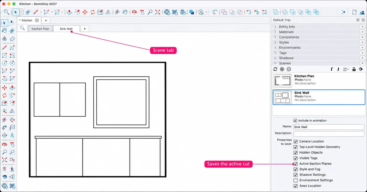
Choose View > Section Planes to hide the plane graphics for a clean view. That changes the graphics, not the active cut. Update the scene after settling its final display. Click another scene, then return to the wall scene: the right cabinet run, camera and cut should return. Repeat for each cabinet wall, checking window heights, service positions and the space reserved for appliances in the view where they matter.
Put the saved views on the drawing sheet
With the Pro route, save the SketchUp file, then choose File > Send to LayOut. Select the model viewport on the sheet and choose the named scene from its Scene dropdown in the SketchUp Model panel. For a scaled plan or elevation, use Ortho and a scale preset or custom scale. The sheet scale changes how the model fits the page; the kitchen stays at its real modeled size.
Open Arrange and check that it shows Object Snap On. If it shows Object Snap Off, select that item to turn snapping on. Use Linear Dimension and snap its connection points to the intended model points, then compare one known cabinet width with its SketchUp measurement.
LayOut distinguishes model dimensions from paper-space distances, so a line across the page isn't proof of the cabinet's size. After geometry changes, check for dimensions shaded red, which flag a possible connection problem.
If a flagged dimension is incorrect, double-click its red text. Drag each red connection dot away from its attachment and back to the correct model inference point. Click outside the dimension, then recheck the value against the model. These layout views communicate the arrangement; fabrication still needs the actual parts, fittings and maker's details.
Save the drawing sheet, then go back to the SketchUp file and click Kitchen Plan and each wall scene in turn. Every tab should bring back its camera, tags and cut on the same editable cabinet run; if one doesn't, set that view again and choose Update Scene.