SketchUp for interior design: from floor plan to furnished room
Start with measured room dimensions and separate containers. Build the shell, cut openings, check furniture and finishes, then save the scene properties your LayOut views need.
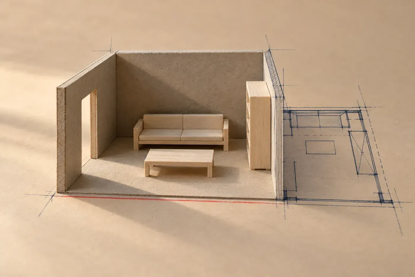
Build the room at its real size, keep its walls and furnishings in separate groups or components, then save the plan, elevations and perspectives as scenes. That is the useful core of a SketchUp interior design workflow: one room model supplies the views you use to decide on a layout. Choose Pro if those views need to become LayOut drawing sheets; Free covers personal browser modeling, and Go adds paid web and iPad work.
I'd settle the room dimensions before choosing detailed furniture, because a convincing sofa cannot repair a floor plan drawn at the wrong scale. The walkthrough below uses desktop SketchUp on Windows or Mac. The browser and iPad plans share the modeling purpose, but their controls and import routes differ.
Choose the plan by what you need to hand over
| Your job | Plan and surface | What changes the choice |
|---|---|---|
| Plan your own room and show it on screen | Free in a browser | Free is for personal, non-commercial use. |
| Do paid room modeling in a browser or on iPad | Go | Paid web file exchange includes DWG/DXF; Go also includes the iPad modeler. |
| Deliver LayOut sheets or use desktop extensions | Pro on Windows or Mac | Go does not include the desktop app or LayOut. |
| Get V-Ray within a SketchUp bundle | Studio on Windows | Mac rendering uses a separately licensed renderer compatible with the host version. |
Free's non-commercial restriction applies even when its tools can draw the room. For client work, Go supplies web and iPad access, including subscriber DWG/DXF exchange in the browser. Pro adds desktop SketchUp and LayOut. The Studio bundle is Windows only; Trimble also documents the direct Chaos route for Mac V-Ray users.
Name the views, then separate the room's parts
Before the first wall, decide which scenes the file should contain. For one room, a useful starting set is Plan - furnished, Elevation - window wall and View - from the door. Add another elevation when a wall needs its own dimensions, or another perspective when it answers a different design question.
Designer Sarah Amos describes starting with a block model and saving elevations, a plan and perspective scenes before moving to LayOut in Trimble's account of her interior design process. The useful principle is to make those views repeatable. Moving a wall aside for a presentation changes the model; a section plane cuts the view while keeping the geometry in place.
Make the shell a group and repeated furnishings components. Groups and components keep geometry from sticking to neighboring parts; editing a component definition updates its copies. An example tag plan is:
Walls: one group containing the walls and floor.Openings: separate door and window frame components.Furniture: loose furnishings as components.Built-ins: fitted cabinets and shelving as components.Plan image: the imported drawing, hidden in presentation scenes.
Assign those tags to the containers. Keep the edges and faces inside them Untagged, as Trimble recommends for tag organization. Tags control visibility; they do not keep loose geometry apart. In SketchUp 2027, the Tags panel lives in the default tray under Window > Default Tray. On an older Mac version, open the dialog from the Window menu; the Mac interface changed in 2027.

Import the plan and verify its scale
Start in an empty model. Open Window > Model Info > Units and choose the units you need. SketchUp lets you use different units for length and area, so millimeter dimensions and square-meter finish quantities can share one model. Model Info's Units settings also control display precision.
- Choose File > Import, select a JPG or PNG plan and choose Use As Image. Click to place its first corner, then its opposite corner. This creates an image entity, following the desktop image-import workflow.
- Set Camera > Standard Views > Top, then Camera > Parallel Projection. The plan should lie flat on the ground plane.
- Activate Tape Measure (T). Click the two ends of a known dimension printed on the plan, type its real length, for example
4.2m, and press Enter on Windows or Return on Mac. Accept the prompt to resize the model. This Tape Measure operation scales the entire model, which is why it comes before the walls or furniture. - Measure a second known dimension without entering a new value. Check one length in each main direction. If they disagree with the drawing, check the picked points and whether the image is skewed or distorted. Use an undistorted plan or draw from the written dimensions before continuing.
- Assign the image to
Plan imageand lock it from its context menu. For a DWG/DXF source, use the relevant CAD import route and verify a known length before tracing; do not assume the incoming units match your model.
If there is no reliable source plan, draw the room from measured lengths instead. All dimensions below are examples, so replace them with the actual room, wall and opening sizes.
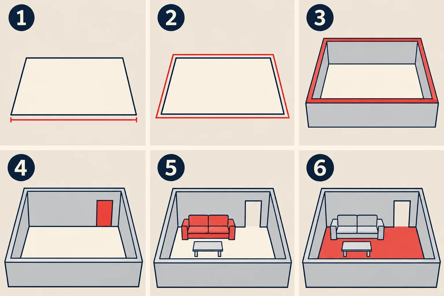

Raise the walls without joining them to the furniture
- Use Line (L) to trace the inside boundary of the room. Keep the edges on the ground plane and close the last edge at the first endpoint. A filled face confirms that the loop is closed and coplanar.
- Select Offset (F), click the face and move outward. Set a precise wall thickness, for example
150mm, and press Enter or Return. Offset makes the parallel outer boundary; the wall band should be a closed ring around the floor face. - Use Push/Pull (P) on that ring. Move upward, set the wall height, for example
2.7m, and confirm. The floor face stays at ground level. - Select the walls and floor, then choose Edit > Make Group. Assign that closed group to
Walls. Open it to measure an inside room dimension, then leave the group and context-click Lock when the sizes are correct.
For a simple room, keep this shell together. Separate room parts only when the project needs independent editing or visibility. The next object you add should arrive outside the wall group, so moving a sofa cannot stretch a wall face.
Cut the openings, then add frame components
A door needs a hole through the shell and a frame in that hole. Work on the hole inside the wall group; model or place the frame outside that group.
- Unlock the shell and double-click it with Select. Its dotted editing boundary should surround the wall geometry.
- Activate Rectangle (R) and draw on the wall's inside face, with a door's bottom edge on the floor line. Enter the required length and width in the Measurements box, separated by a comma, as the Rectangle tool accepts precise dimensions. Check the width and height with Tape Measure before cutting.
- Select Push/Pull (P), click the opening face and push toward the outside face until SketchUp reports that the offset is limited. Click to finish, then look from the other side: the opening should go all the way through.
- If it stops as a recess, check the opposite face. Push/Pull needs parallel faces and an undivided opposite face to cut through. Save a copy before removing edges, and erase only an edge you have identified as an unnecessary divider. Keep the wall outline and the edges defining other openings.
- Leave the shell, select the frame geometry and choose Edit > Make Component. Give its Definition a useful name, click Create, place it in the hole and assign
Openings. Edits to a component definition reach all its instances; make a separate definition when a frame genuinely differs.
The component option Cut Opening cuts an opening in a face. For a wall with real thickness, explicitly making the through-hole keeps you from mistaking a cut in one face for a complete doorway.
Measure furniture before detailing the room
Open the Components panel's Select tab and use its 3D Warehouse search, or choose a model on the Warehouse site and click Download. These are Trimble's documented ways to bring in components. Begin with simple blocks of the right size when the immediate question is whether the furniture fits.
After inserting a piece, measure its width and depth against the manufacturer's dimensions. Certified Content is checked for real-world scale, orientation and organized geometry, and subscribers can filter for it. Still check the dimensions of the exact product you intend to specify. A similar-looking chair is not evidence that a different model will fit.
If a downloaded component needs uniform scaling, select the closed instance and use a corner grip with Scale. Scaling its contents after opening it changes every instance of the definition. Avoid stretching a manufactured sofa to fit a gap: its modeled width would no longer represent the product. Place loose furnishings on Furniture and fitted pieces on Built-ins.
For paid work, the 3D Warehouse Terms of Use FAQ permits a paid design containing downloaded models as a Combined Work. It does not permit selling those models as stand-alone items or aggregating them on your own website. The full terms govern the use; a Warehouse download is not a license to redistribute a supplier's model library.
Apply finishes and keep the quantities meaningful
Open the wall group to reach its floor face. Activate Paint Bucket (B), choose a material on the Materials panel's Select tab and click that face. Materials can be applied to faces or to whole groups and components, so check which level you are painting. If the finish does not appear, check whether the current style displays materials before changing the geometry.
For a finish presentation, choose a style using Display Photoreal Materials and select an environment in the Environments panel. Environments supply image-based lighting and reflections; some library environments mute overhead light for indoor use. Save the chosen environment with the presentation scene.
To total a finish, context-click its material and choose Area > Material. The total includes faces painted with that material, using the model's units. Use a material reserved for the relevant finish, inspect which faces carry it, and keep the purchasing allowance for cuts and waste separate from the modeled area.
Save the elevation with its camera, tags and cut
Leave all groups before placing these presentation section planes. Only one section plane can be active in each model or component context. Keeping this set at the model level makes the scene's active cut easier to track.
- Choose Tools > Section Plane. Place it on a vertical face with the orientation needed to reveal the target wall, and name it, for example
Window wall. - Move it into position. Context-click Reverse if it removes the part of the room you need to see, then choose Align View and Camera > Parallel Projection. Set this plane to Active Cut.
- Use View > Section Planes to hide the plane graphic while leaving its cut active. For filled cut walls, use Styles > Edit > Modeling Settings > Section Fill. The cut geometry must form closed loops for the fill.
- Hide
Plan imageand choose the furniture visibility needed for this elevation. Open Scenes, click Add Scenes and open Show Details. Name the sceneElevation - window wall. - Keep Camera Location, Visible Tags and Active Section Planes selected. Include Style and Fog for the chosen style, and Environment Settings for a finish view. The scene's saved properties determine what returns when you select its tab.
- Click another scene and return. Check the camera, cut direction and visible objects. After revising those settings, choose Update Scene; merely changing the current view does not update the saved scene.
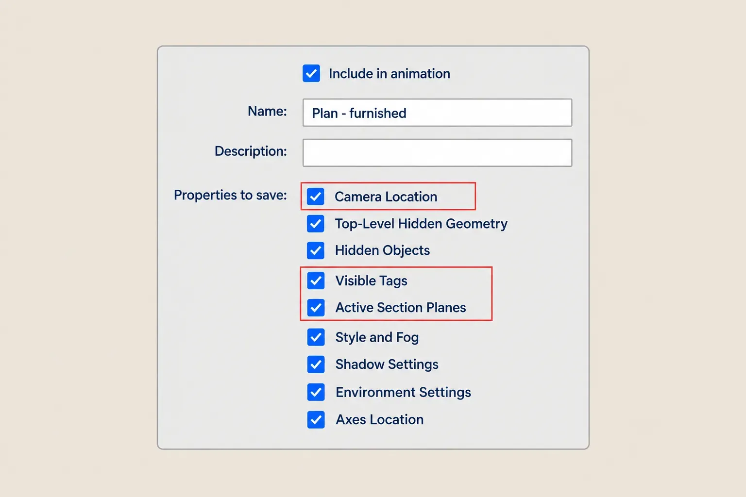

For View - from the door, deactivate the cut and compose a perspective before adding the scene. Keep presentation views distinct from measured plan and elevation views, which use Parallel Projection.
Use a render for a specific design decision
The modeler's material-and-environment display is useful while discussing finishes. A separate renderer makes sense when you need controlled artificial lighting, a finished still or a panorama. Sarah Amos pairs SketchUp with Enscape in the customer story above; Studio includes V-Ray on Windows, while a Mac purchase needs the renderer's own supported-version check. These are different routes, not a renderer ranking.
I'd render the saved views the client is deciding between, because the same camera makes a change in layout or finish easier to judge. Keep the furniture dimensions fixed while comparing materials. A light-fixture model shows the fixture's shape and position; light levels require the actual fixture's photometric data and an appropriate lighting calculation.
SketchUp's Analysis Hub separates Advanced Shadows from its Public Labs daylight analyses. That is a different question from calculating a specified pendant's output. Check electrical requirements and applicable building rules with the responsible designer or local authority before using a drawing for installation.
Keep reports separate from purchasing decisions
Generate Report can count component definitions and export a CSV, with attributes such as Price or Size. Its Component Quantities template is a useful model inventory, but it counts what you modeled. Maintain supplier details, approvals and order status in a separate schedule so a duplicate chair instance does not silently become an extra purchase.
For an attributed example of the wider document set, Clare Le Roy describes creating cabinetry, scaled drawings and lighting plans in LayOut in her interior design workflow; her site also offers a separate fixtures-and-finishes schedule. LayOut can import CSV and Excel tables. Keep the master schedule where you can maintain its purchasing information, then use the drawing to communicate the relevant selection.
Finish on Plan - furnished and its LayOut viewport
With no group open, place a horizontal section plane on the floor and name it Plan cut. Use Move (M) along the blue direction, holding Shift to lock that direction, and enter the cut height appropriate to your drawing, for example 1.2m. Reverse the plane if it hides the floor. Tall cabinets and other objects crossing that height will be cut too.
Turn on the room and furnishing tags, hide Plan image, make Plan cut active and choose Camera > Standard Views > Top with Parallel Projection. Add the scene Plan - furnished, keeping its camera, tags and cut saved. Switch away and back to verify the result, then save the SKP.
On Pro, choose File > Send to LayOut. SketchUp prompts you to save, then LayOut creates a document viewport. Select that viewport and choose SketchUp Model > Viewport > Scene > Plan - furnished, as the scene-selection controls describe. Give each elevation its own viewport and set the drawing scale before adding dimensions. The saved scene is the view you can return to when the room changes.